Over the years I had searched for information on the blaster, finding sites like the "Parts of Star Wars" and others that told what all the pieces were that went into making the original props. Like many other Star Wars fans, I spent my fair share of time drooling over GOOGLED images of Sterlings. I searched for tutorials or websites showing the conversion process by someone who had done it, but turned up very little. A few sites showed some pictures, but lacked the detailed photos and descriptions I was looking for. It wasn't until later that I actually thought of trying to find a Sterling and do the conversion to screen-accurate prop myself.
I looked around, and discovered that most Sterlings are cut up and sold as parts kits . . . in pieces that must be welded back together, or welded onto a new barrel. IMA-USA had some of these kits, but they were all still chopped up. The Sterlings that exist in the U.S. today are all that will ever be allowed in, as importing them has been banned.
During the searching, I also found a Sterling Manual:
STERLING MANUAL 3.4 M
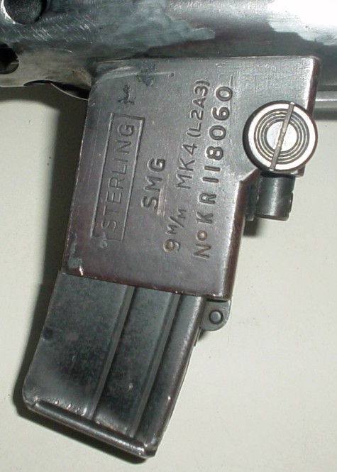
It was January of 2007 that I made it the other halfway there and found the starting point for the journey. I obtained a deactivated Sterling L2A3 MK4 submachine gun from a fellow Legion member from the Golden Gate Garrison.
This blog will show you the process I went through to create the prop I own today.
ALL pictures are clickable for larger versions. Once the larger versions have been viewed, be sure to click the BACK button on your browser to return here.
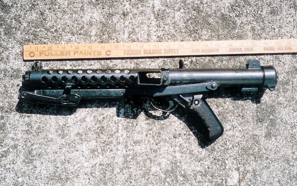
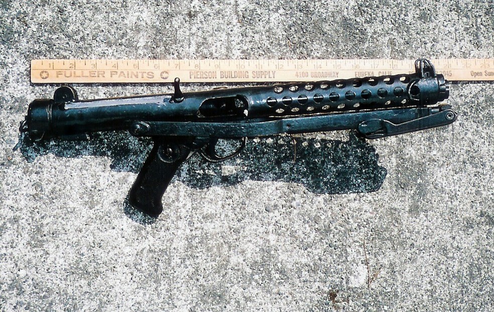
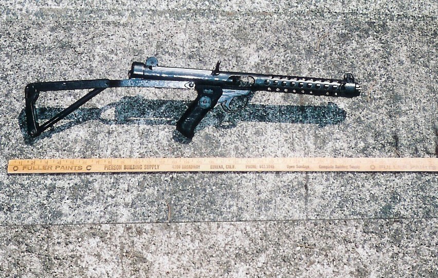
These are the first, emailed pictures I received from California of the Sterling that was being shipped to me:
I found a supplier for the rigid T-Tracks that are used for the blaster fins (along the cooling vent holes) on the RPF or Replica Props Forum. Originally it was thought that rubber was used, but it was actually cheap, T-shaped kitchen drawer track. I also had the good fortune to find someone who had uncovered a small supply of Hengstler counters with the Eagle logo on them, so I quickly placed an order for both items.
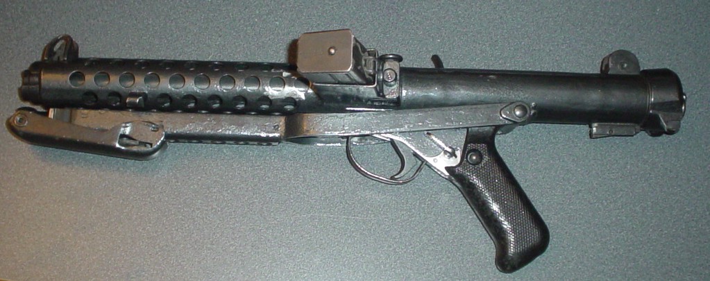
Then, on Feb 5th the Sterling arrived. It was in fantastic shape!
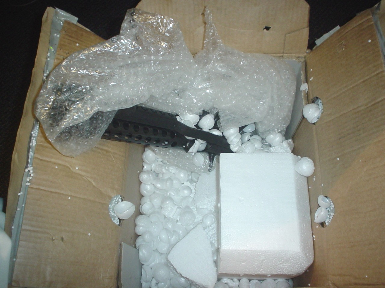
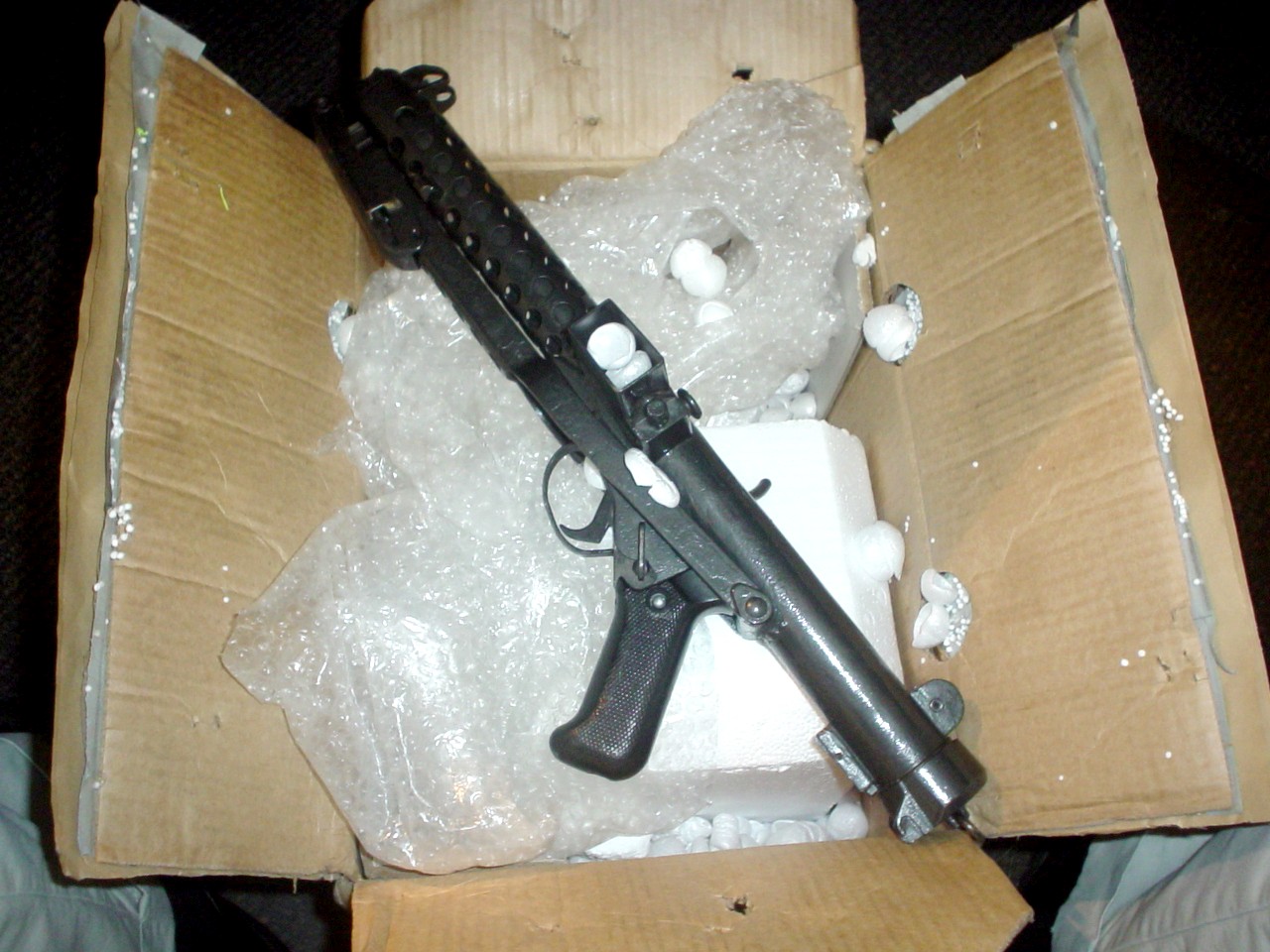

The emailed pictures really didn't do it justice. They seemed to indicate more of a bare metal finish. In reality, the chipped, mottled paint had never been fully removed, simply painted over without removing the old paint, or attempting to smooth it out at all. I would definitely be stripping the paint off, trying to make a smoother finish to paint over.
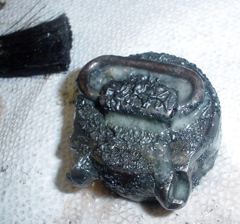
It was heavy with a SOLID metal plug where the bolt would normally be, but still not too bad. It felt the way a real blaster should feel, with some ASS behind it! A HUGE difference from the Kenner! The rear end cap did come off to reveal the end of the solid plug. I decided to drill some of it out to reduce weight.
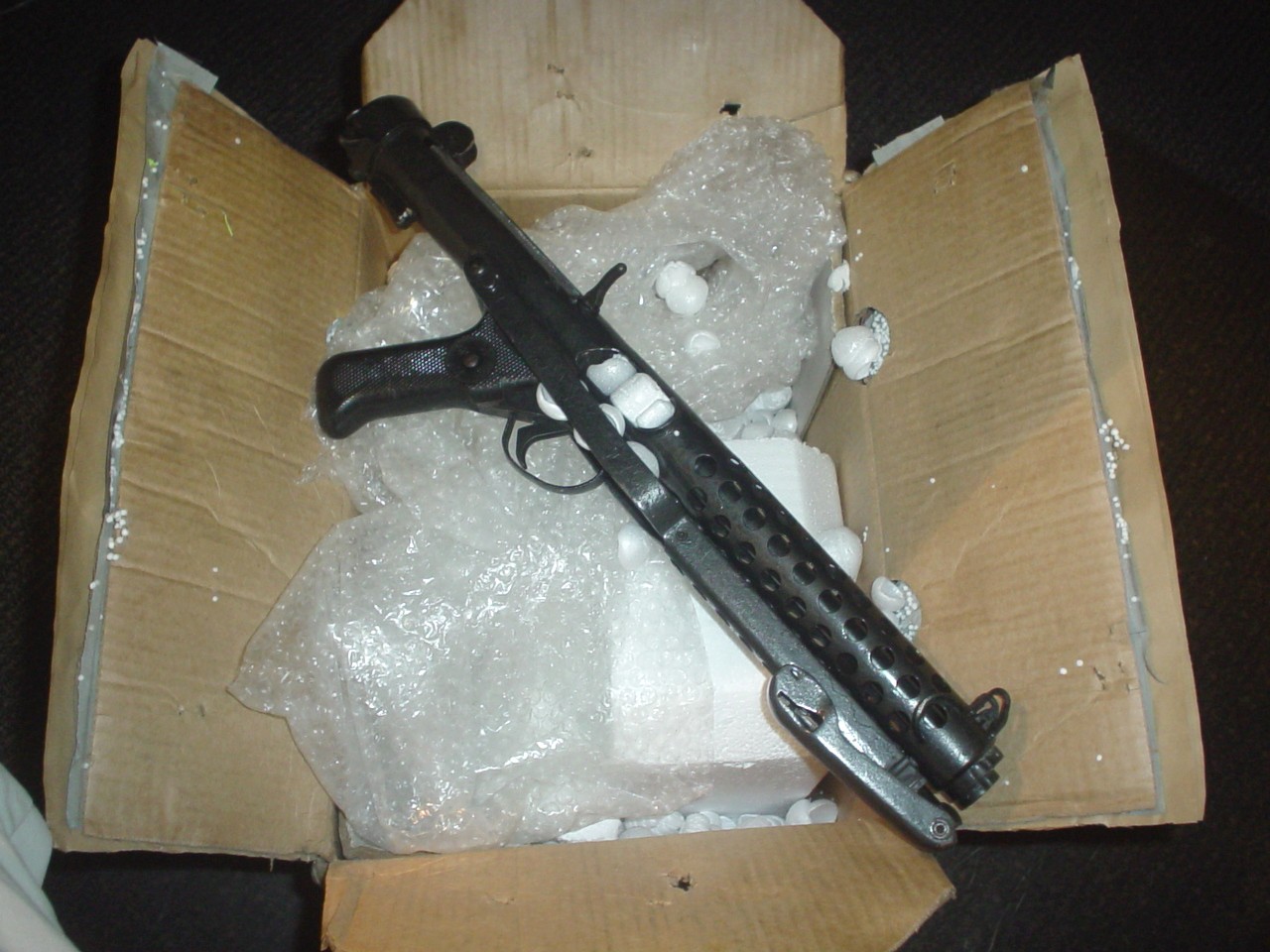
As seen here, I unlatched and opened the stock . . . very cool.

It did not come with a magazine, so I went to http://www.ima-usa.com/ and ordered a 34 round Sterling mag. Soon afterward, the other pieces I had ordered began arriving as well . First the Hengstler:
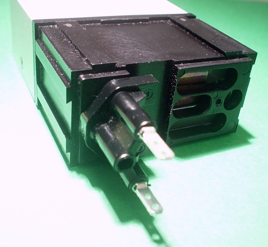
I couldn't resist setting the counter to my TD#

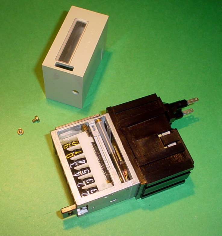
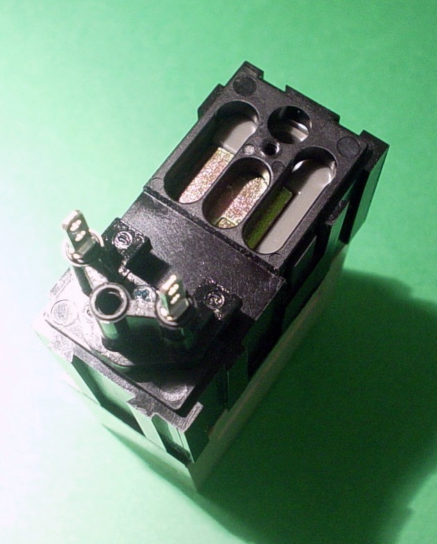
And for anyone interested, here's what the insides of a Hengstler look like:
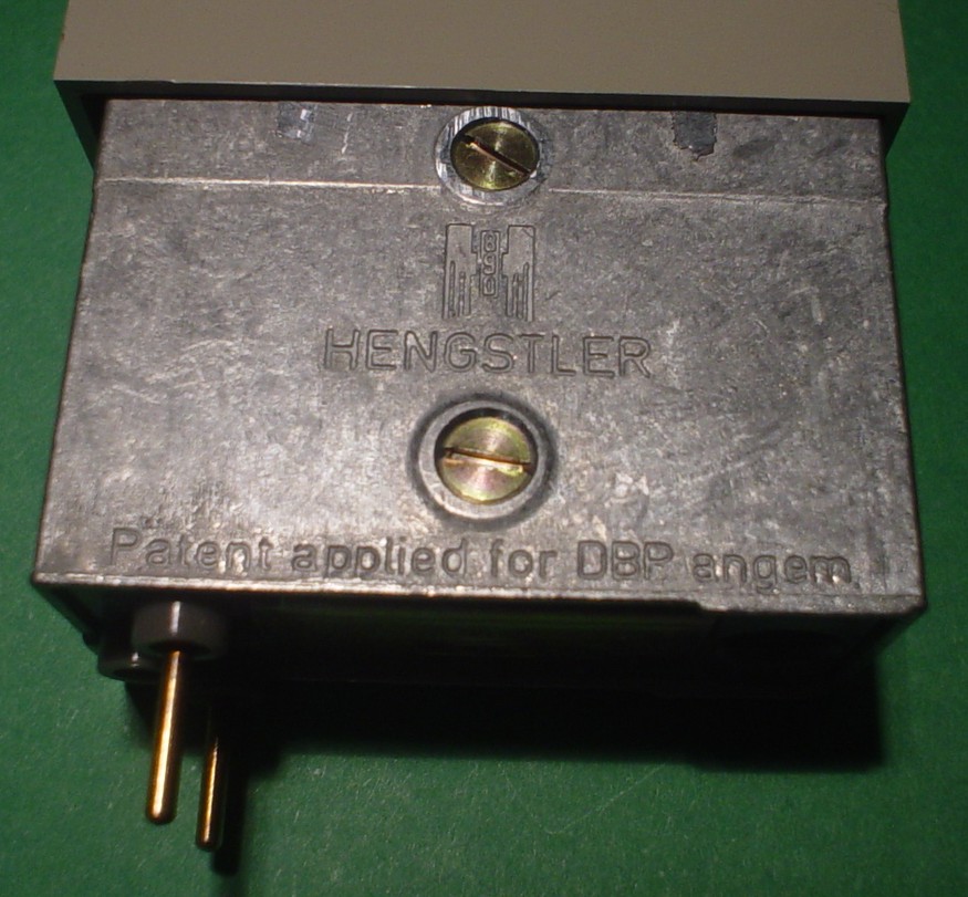
OH, and yes, the Eagle logo:
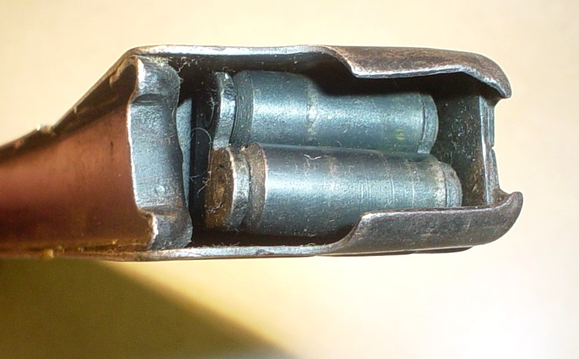
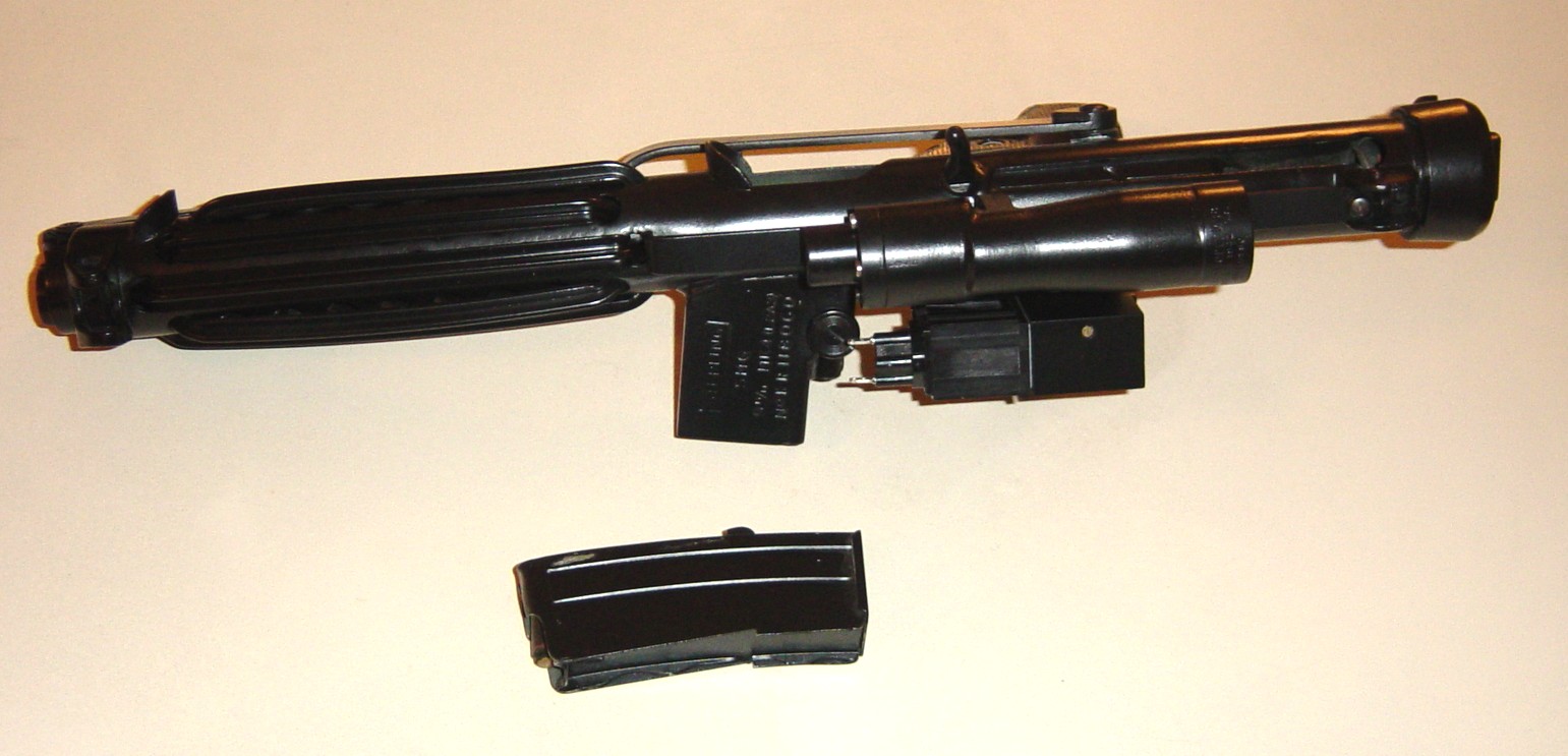
 Next, the magazine arrived:
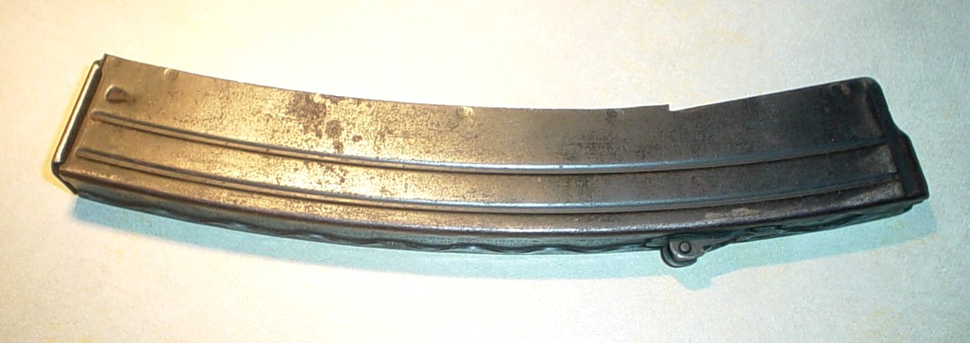
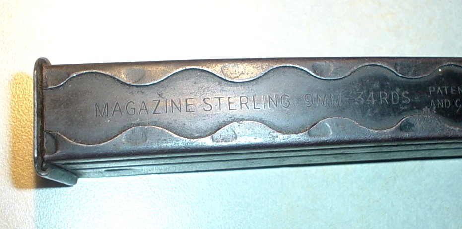

 The magazine was WAYYY longer than seen in the films and needed to be cut down for my prop. I made sure to keep the part that was stamped STERLING 9MM 34 RDS as a souvenir. Here is the process of the cut-down and installation in the gun afterward:
 The tape marked where I wanted the mount to end up, so I cut about an inch or so beyond the tape to allow me enough material to bend back and form the new "guides" that the end cap would slide on over. So I cut the magazine down:

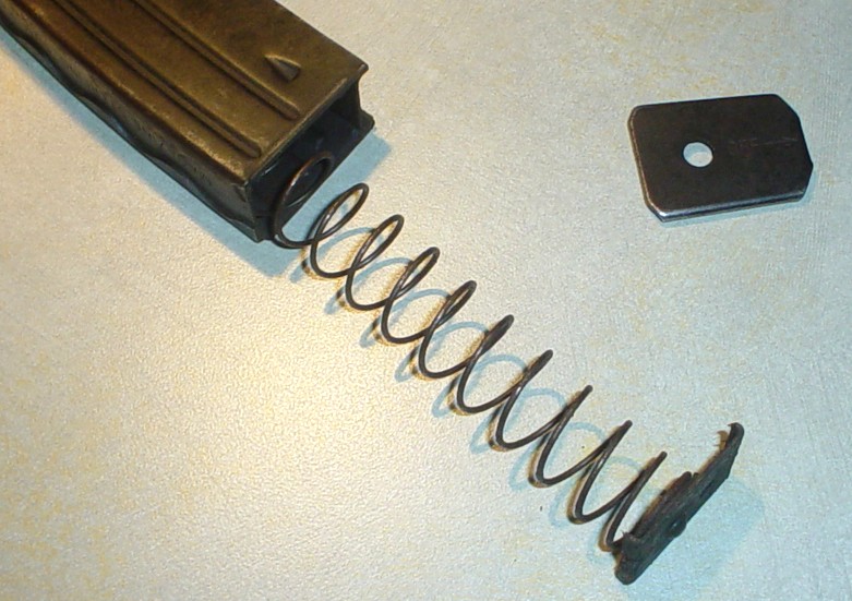
Then I cut along the seam lines, and across the edge, which would allow me to fold the sides back and create the "guides".

Here are the side seams folded back, and ready for trimming down:


Then I cut along the bend, careful to leave some of the curvature intact, which would become the new "guides".


My T-Tracks arrived from Malaysia on Valentine's Day.
They are stiff, but bendable plastic. They needed trimming and heating to bend and fit into the holes, but are now being considered more accurate than rubber for the E-11 grips.
Their origins are as inexpensive drawer guides. They were cut and stuck into the vent holes on the original props, and on the MG-34s, they had wire wrapped around them to keep them in place.

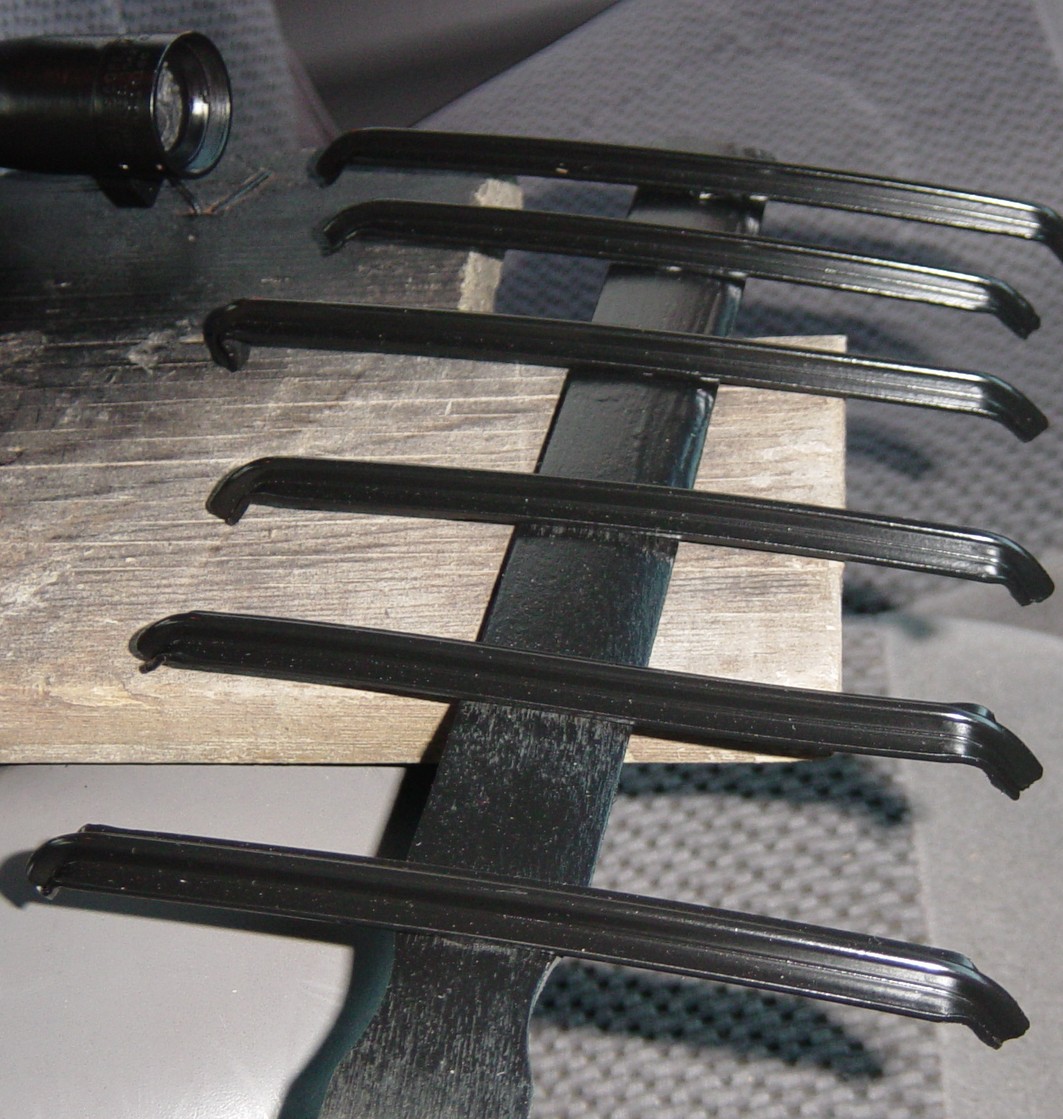
Here is the process I went through to create the vent hole covering fins:
I bent, cut and fitted the T-Track grips on the Sterling.
I started by carefully heating the tracks waving a lighter beneath them and rolling the track in constant motion so as not to warp or burn it:

This is the angle that seemed to work best for staying in the holes, and allowing the track to lay FLAT against the barrel.

Once bent, I snipped an angled piece off the ends with wire cutters and used a razor knife and sandpaper to shave off and round the edges of the tracks for a better, snug fit down into the holes.
With one end correctly dropped in, I marked the bend point for the other end. I determined that midpoint of the end hole was about where it needed to be.

Here are the results:


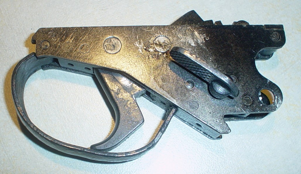
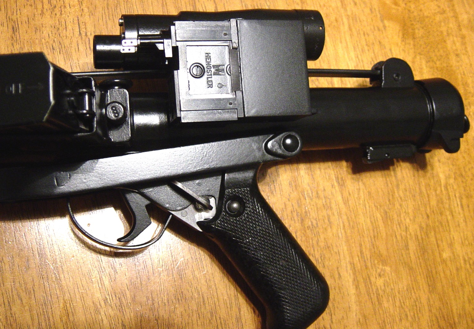
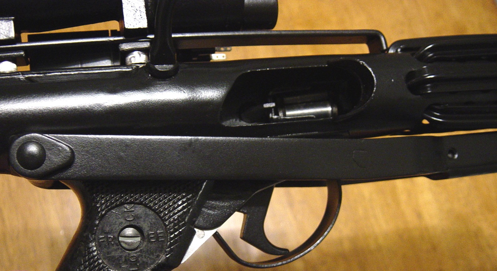
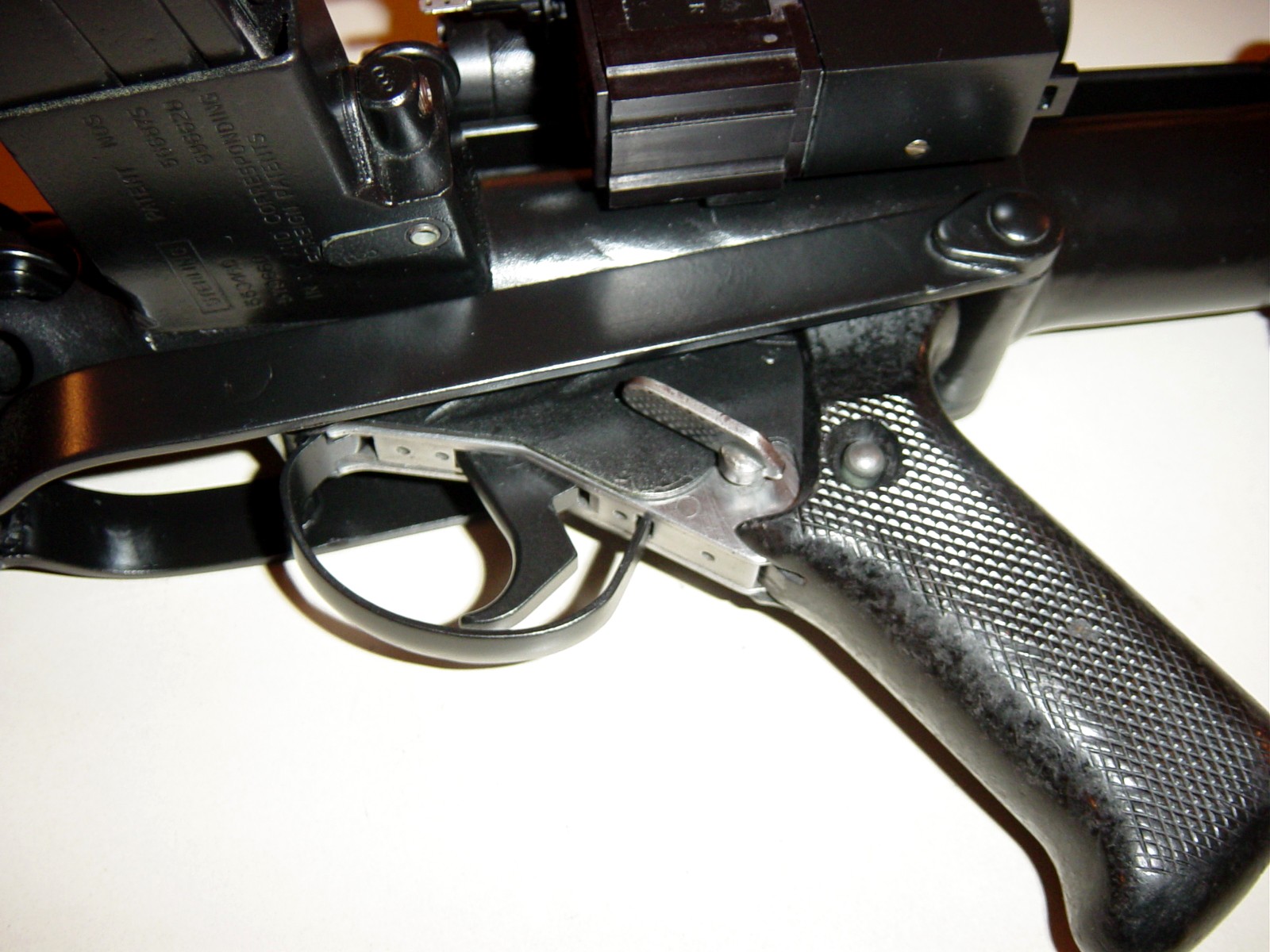
When the Sterling arrived, the selector switch did not work, so I removed the grip and trigger assembly. Prior to doing so, the trigger was able to be pulled just slightly, and the selector switch would not move. Once the grip and trigger assembly was removed, the selector switch works fine, and the trigger squeezes all the way in.
Here are some pics:

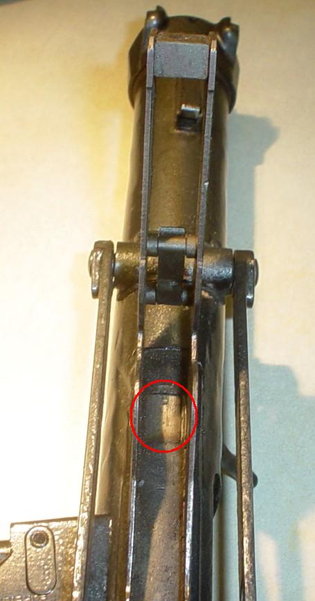
I thought if I ground down the tip of this part (circled in red) the trigger and selector may work when reassembled.
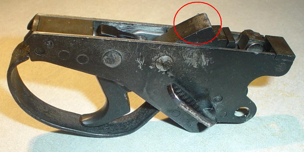
If not, I thought maybe drilling out a recess in this area for it to slip into the solid plug in the barrel.
On Feb 16th, I began stripping off some of the thick paint layers on the stock. I had no idea the paint layers were so thick. I could see that there were several layers, but it took a bit longer than I expected.
I worked by hand with sandpaper to ensure that I got into hard to reach areas and did not wisk away metal as a drill attachment or dremel might have. It took a while, but was worth it. The side of the stock that I stripped is nice and smooth, the other side is bumpy and uneven.
For the difficult to reach small areas, I used a thick stripping agent I use to strip lacquer and paint off old furniture. It looks like orange phlegm, but works REALLY well.
I started by removing the grip and trigger assembly, and then began dabbing the thick stripper on the painted areas.
Here's a picture of the stripping agent used:

And here are some pics of the Sterling as the chemicals were working on the paint. You can see it bubbling and rippling as it melts away from the metal:


And here are a few pics of it after the stripper has been wiped away with a paper towel:


Here's a side-by-side pic to show you how much even just the stripping has helped:

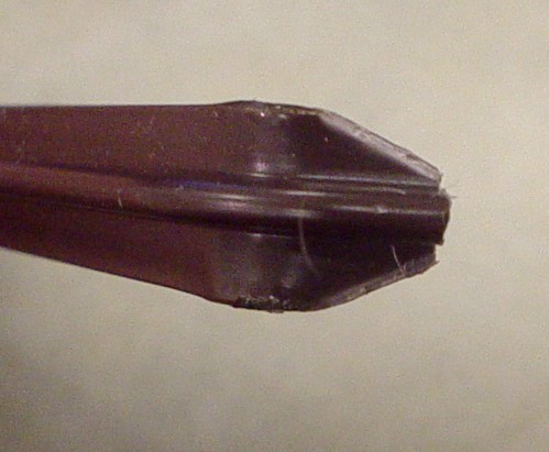
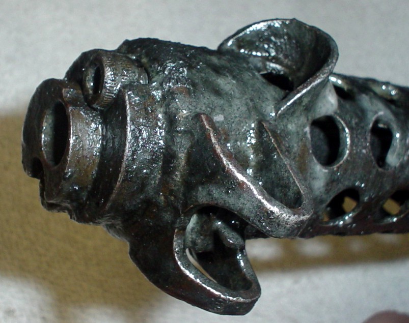
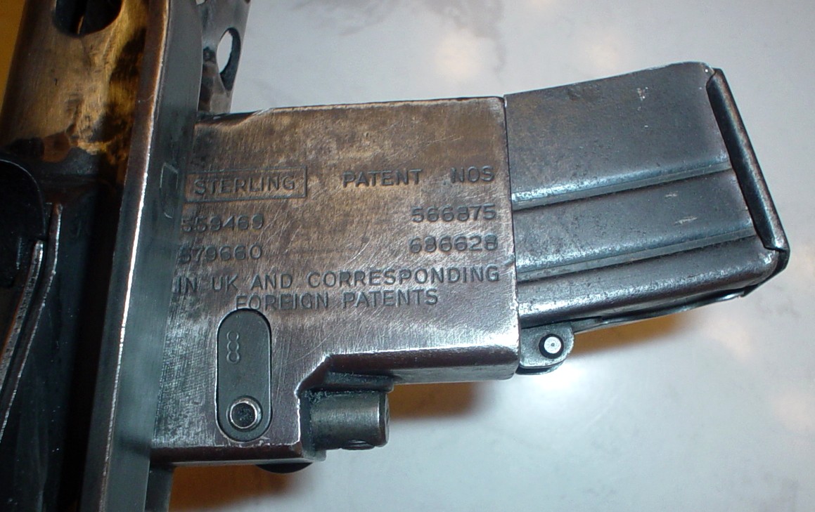
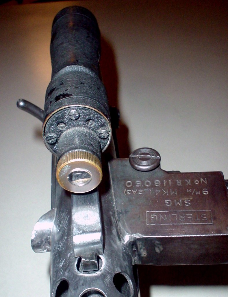
A bit of trivia I thought I would share about the unusual barrel end on the L2A3.
I always wondered about the offset circle in the front.
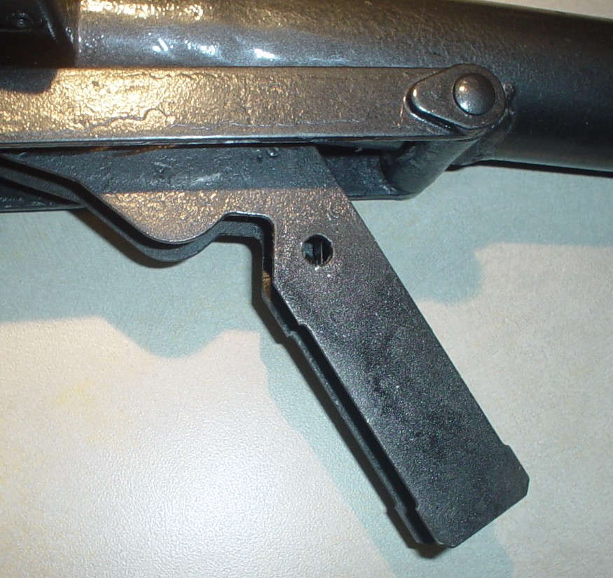
The government came up with the idea that the Sterling HAD to take a bayonet, and utilize one already in circulation. The trouble they had was that the diameter of the gun with the cooling shroud was larger around than a regular rifle, so they had to offset it to use the older bayonets. The offset circle at the barrel is for the hilt of the optional bayonet to fit over, like on a rifle except thrown further out to the side to MAKE IT FIT (Seen here, circled in red):

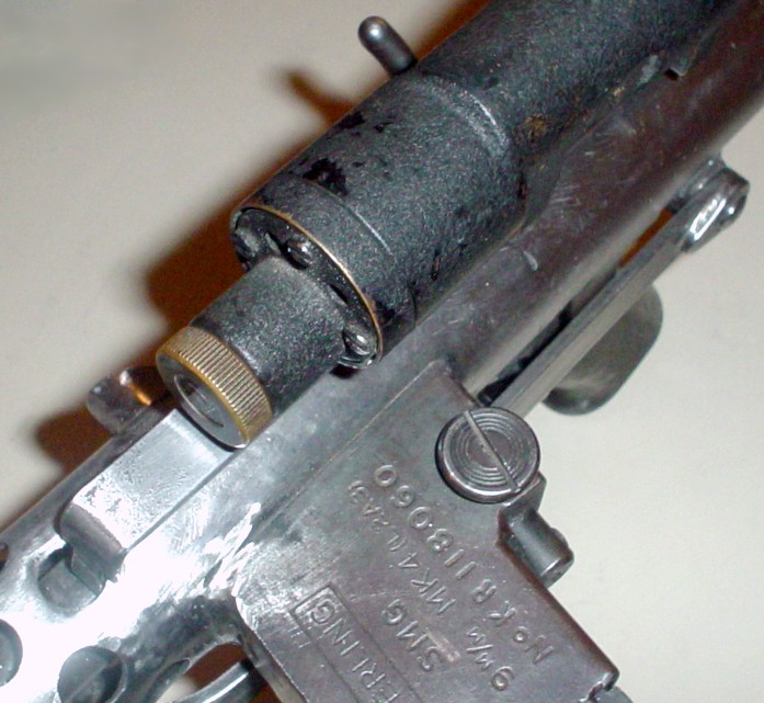
There is also a flat area in front of the bayonet mounting nub (underneath the shroud on the Hengstler side) where the gun was machined to accommodate the bayonet attachment.

Thought that was cool, and I would share it.
On March 8th, I found an authentic M38 Tank Telescope for the conversion process at www.checkpointcharlies.com :
This was the picture on their website:

Now the only thing that won't be real-world accurate is the power cylinders on the top of the mag well, and I will get those as close as possible, if we don't identify them first.
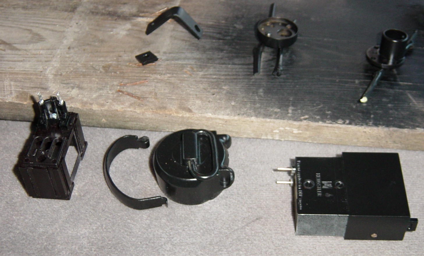
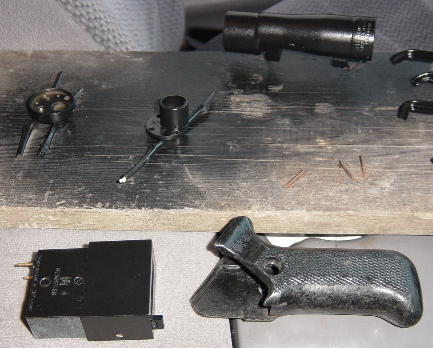
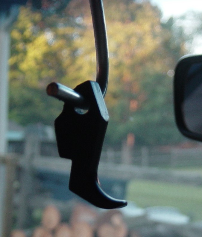
When the scope arrived on March 13th and was waiting for me after I got off work.
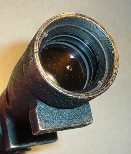
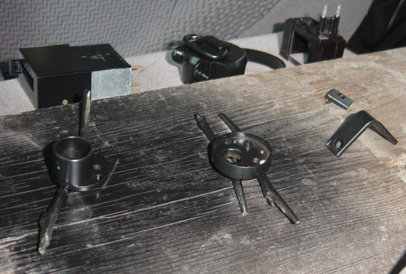
Here are a few pics I snapped of it:


The knurled brass piece in the front (actually the part you look into) is for fine focusing adjustment.
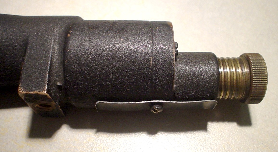
The little clip thingy underneath holds a small bearing in place inside the end of the scope for the threads of the focusing ring to ride on. It is spring loaded so you can pull the focusing ring out quickly without having to unscrew it all the way.

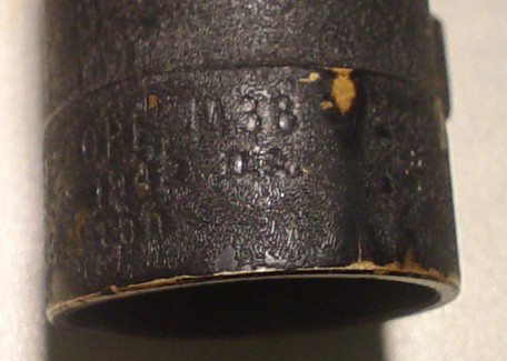
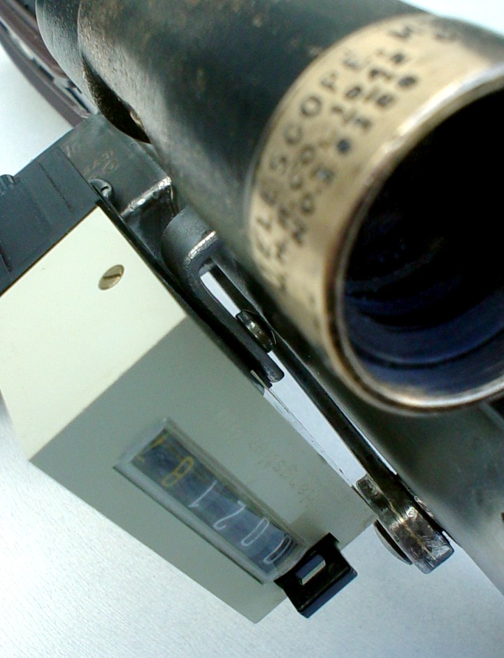
Yes, I checked to make sure it's a real M38:
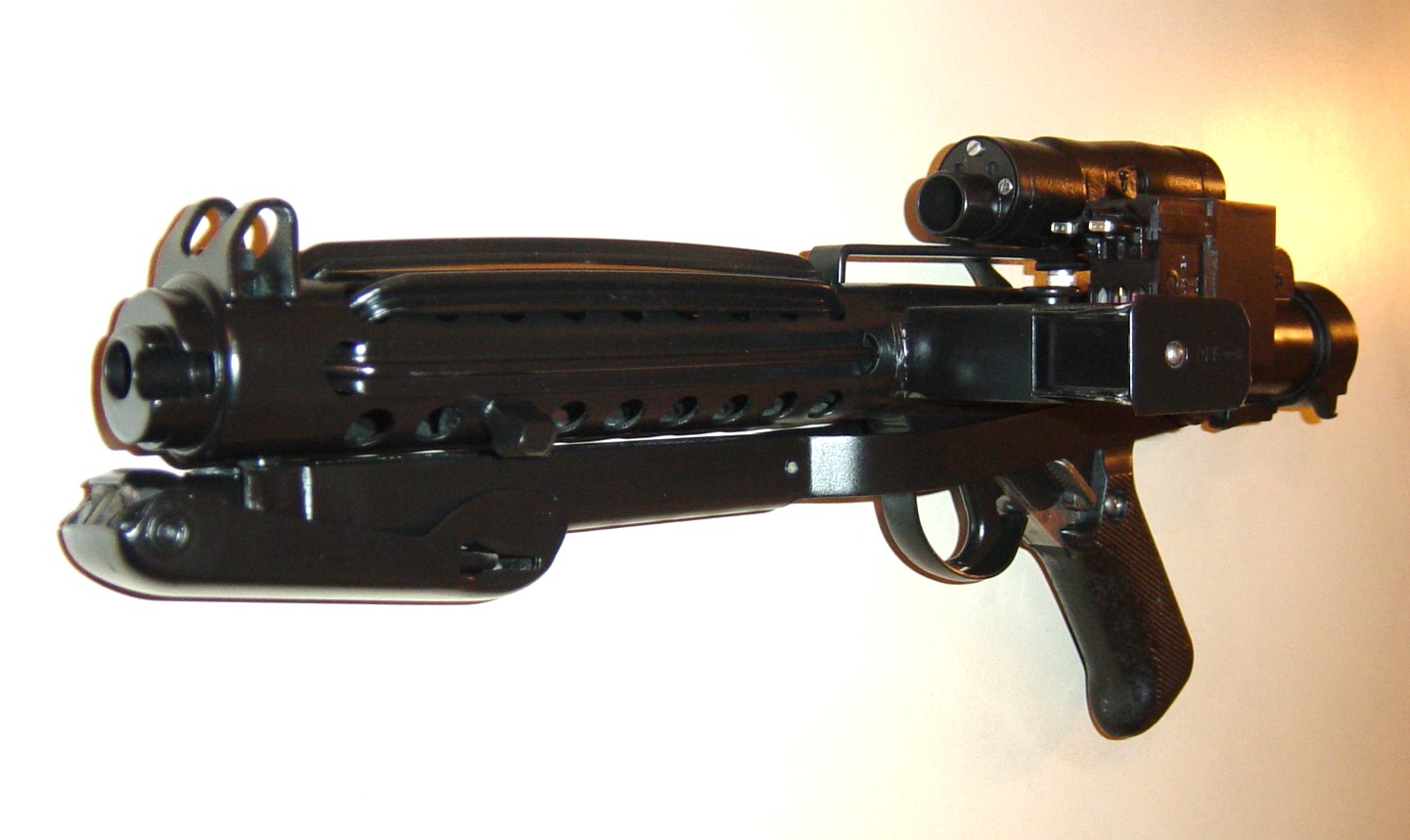
Here are a few test pics of it sitting on the scope rail:
And a VERY impromptu picture (with terrible lighting) of the basic layout of things. I think the scope will actually end up being mounted back a bit further, so the Hengstler mounting bracket will line up with the front scope mounting bolt.

All in all, I was one HAPPY Sandtrooper!
The next night, I applied the same stripping agent used on the Sterling (earlier in the thread) and the gummy, Parkerized finish was bubbling after about 5 minutes. I let it sit for 10 and then wiped it clean with a paper towel. Check it out:


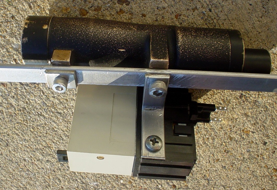
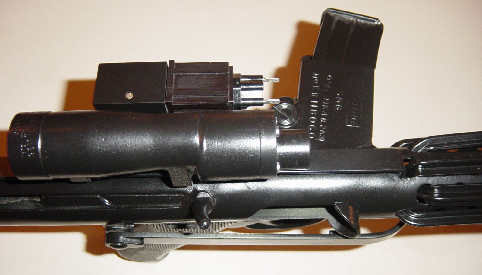
Over the weekend of March 17th and 18th, I worked on the mounting the scope and counter to the scope rail.
Here's the pic of everything mounted on the rail:

Here's showing a bit of HOW it is attached. I used the same material I used for the rail itself (a steel bar used to support hanging files in a wooden desk drawer!). This makes the counter arm VERY strong.

And here are a few of the asembly on the Sterling.

Judging from this picture, I need to loosen the Allen bolt a bit and straighten the counter, but you get the idea.


I don't know if anyone knows the TRUE origins of the cylinders that mount on top of the magazine well, but I would love to hear it if you know!
I did some research and discovered a few images of the cylinders I was trying to identify, in case anyone else has a brainstorm, or knows vacuum tube amplifiers from the 60s and 70s:
The ones from the top of the Landspeeder, shown below also, are the same:
First, 2 pics from a screen-used E-11:


Then, the top of the Mouse Droid:


The Landspeeder hood showing the same tubes:

I actually made a pretty decent breakthrough while emailing with Paul Harrison from Elstree Studios, London (One of the men who worked on building the Landspeeders and Mouse Droids for ANH).
Here is what he had to say:
Hi,
We built the originals but the art department did a lot of the dressing up. Most greeblie parts came from Elstree Electrical, which was an old store on the high street that had old oscilloscopes, valve radios etc.
But those parts I think were just spark plugs with the porcelain knocked off with tender tap from a hammer! We helped John Stears on the mouse droids too, we had it running around the workshop, based on a Datsun 280 RC sports car from what I remember. I think it was old valves on there. Most glass bits were broken off as we knew they wouldnt survive shipping, it was easier to remove them and repaint.
Hope this helps,
Cheers, Paul
Then I just went online searching for valve radios and found a PDF schematic for a RCA Victor Radiolette R-5 and found this:
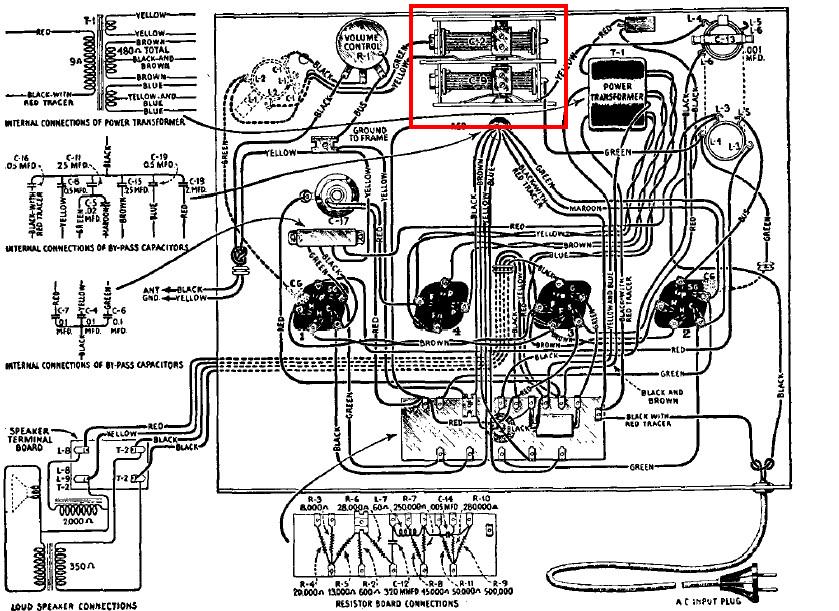
I then spoke with Chris Trevas from the Parts of Star Wars website about it. He had this to say:
Ward,
What we really need to look for is a whole rack of these things. The prop department cut them down into pairs. They came as full racks of 6.
Interesting info, but I can tell you they were racks of 7-pin vacuum tubes. Those are the fragile glass parts Paul remembers removing.
The large empty sockets were identified by the MSE droid builders forum.
Audio equipment is likely the correct direction. I've been focusing my research on amplifiers (which use 7-pin vacuum tubes, often in sets of 6).
Maybe you could ask Paul about amplifier equipment. Chewie's bowcaster and Luke's hunting rifle both have Fender amp knobs on them.
Chris
So I emailed those comments to Paul and he responded with this:
That makes sense, the shop always had big old radios and "portable" amps for musicians which were big things. They had those other amps that went between a record deck and speakers too, I think marshalls were going well by then ?
------------------
Sent from Paul's Blackberry phone www.elstreeprops.com
Hopefully, we are closer to finding out what they are.
It's our estimation that some sort of vacuum tube went in the lower, open receptacles next to the circles cylinders, but we aren't certain.
Since the fitting of the scope rail, scope and hengstler, I busied myself by smoothing out the rear barrel, which had been cut and re-welded.
Next, I picked up the degreaser and etching primer. I stripped the entire gun down and got to work degreasing it and the clip.


Then, I set to priming:


After that dried thoroughly, I went over it with 1500-2000 grit sandpaper to smooth it out a bit. Next came the shooting with a smooth satin black finish.
I took advantage of the AMAZING weather over a September weekend that felt more like late October and shot the black satin paint. I finished shooting and allowed it to set up in the wonderful temperatures. Once it was dry enough to handle, I re-assembled everything.
I removed the bubbled window on the Hengstler counter and have nothing in right now. I had heard that the windows on screen-used blasters were flat, not bubbled, but I kind of like it with nothing, and may leave it that way as my own variation of an A New Hope blaster!
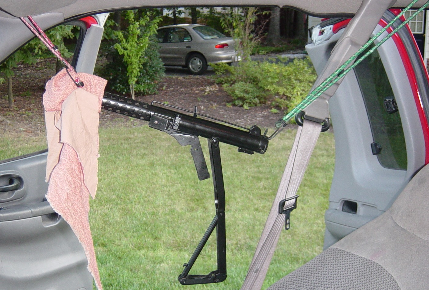
Here are some of the parts drying:
Here you can see the harness I set up inside my truck to suspend the gun while the folding stock dried:
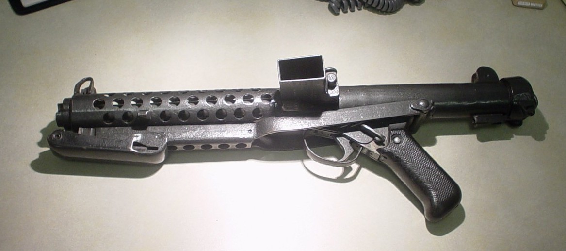
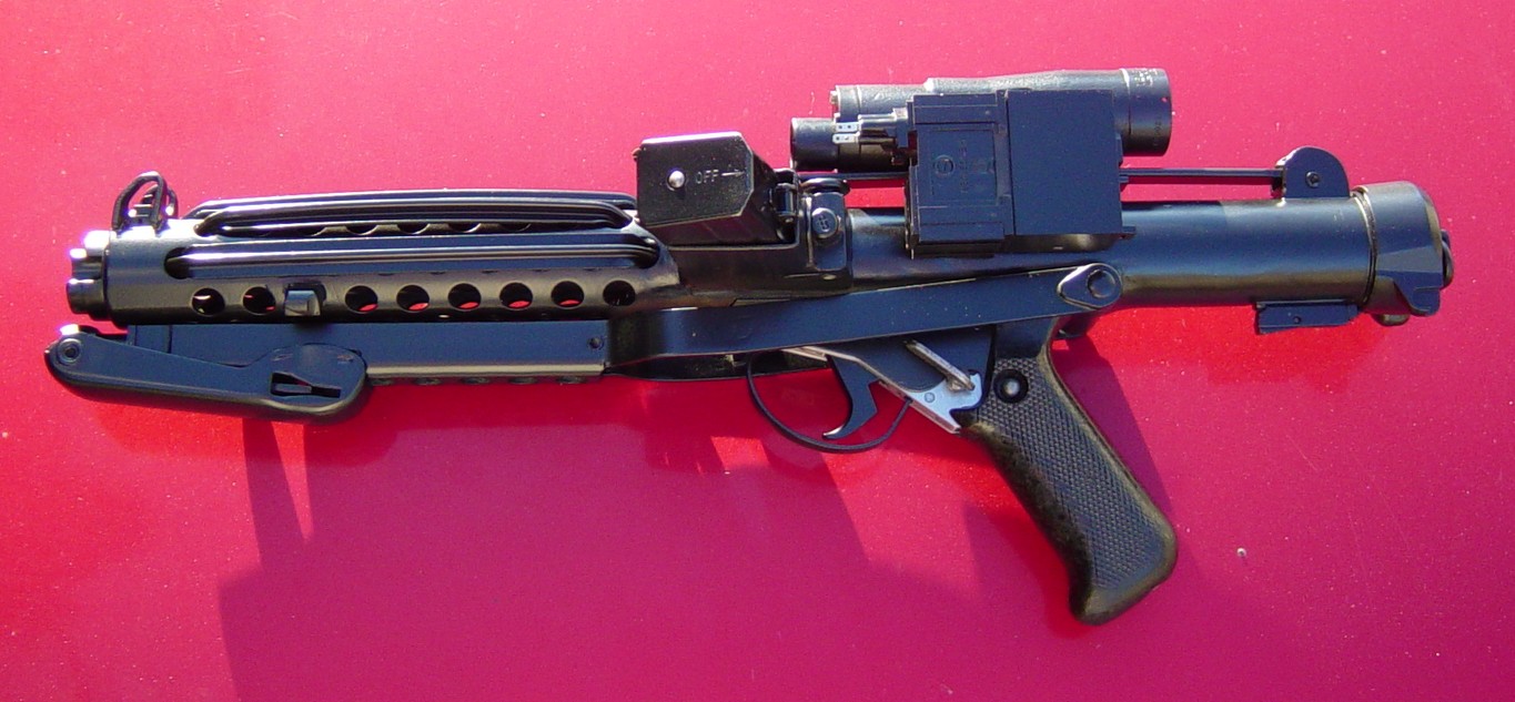
And here are pics of the gun once reassembled:


Here is a pic I managed to snap using the fleeting sunlight for a little more detail. Please excuse the dirty truck hood beneath it!
The last pieces are the cylinders for the top of the mag-well.
I picked up a set of custom made cylinders for just this purpose from Russ Brown.


Now I need to paint them and add the coiled wires from the cylinders to the Hengstler. Then all that remains is to secure the "fins" that cover the cooling vents and build or purchase a display stand.
Thanks for checking it out, I hope you enjoyed it, and if you are converting, I hope it helped you.
UPDATE: I have attached a pair of Rare Earth magnets to the lower plate of the cylinders and sprayed them satin black to match the blaster. the magnets will allow clean, no-damage mounting of the cylinders to the magazine well.
Here are the pics:


UPDATE:
I picked up a piece of solid core wire from Lowe's and spray painted it the
same satin black as the body of the gun. Then, when it was fully dried and cured,
I wound it around a small diameter piece of pipe to give it the coiled look. The solid
core wire helped it keep its shape.
I removed the two lower connection pins from the Hengstler plug and drilled out the holes
to accept the wire - making sure to keep it a snug fit.


My Hengstler had come with 2 plugs, so I removed the one that had been mounted.
There's a small screw holding it in place. Then I simply screwed on the new plug.


When that was in place, I carefully uncolied the wire a bit to give it the shape I wanted,
and forced the ends under the cylinders. I will probably look to secure this a bit better in the future.


I hope this blog has helped yo if you are converting a Sterling, or hope to.
UPDATE !
UPDATE !
I am really excited!
I sent the link to this conversion blog page to Paul Harrison from Elstree Studios, London (One of the men who worked on building the Landspeeders and Mouse Droids for ANH). I had spoken with him before about the magazine well cylinders, and trying to identify them.
Having my work reviewed by this original ANH prop maker is unbelievably surreal.
Here is what he had to say in his email back to me. (His P.S. is about the magazine cylinders):
"Ward, that is stunning work, looks perfect! I actually used to fire these in the British Army, it was the weapon issued to those working inside tanks and mobile artillery units as the SLR rifles were too long to get in and out with quickly.
They are a wicked weapon, hopelessly inaccurate at range but great at close quarters. When firing a long burst, the recoil was so strong we had to aim bottom left of a target and push down on the top of the barrel as it would come up and to the right really hard! They were easy to strip and clean but dirt would easily find its way into the spring area. We used to stick a condom over the end and unroll it to help :)
I've got an ILM stamped cast resin one somewhere in the containers, if I can find it I will photo it for you. Great job, but don't make it too clean or you will lose the look and feel of the movie!
Cheers, paul
P.S. Just had an idea, I have all of John Stears’ droid manuals, were the same valves used on any other droids? The MSE manual doesn't show them clearly, but I have the umbrella droid, stick droid, dome droid and R2-d2 which are more detailed."
I need a better picture, but this is what it looks like completed, and displayed:


28 comments:
Just stumbled upon your blog.
Its always a joy to see my tracks on a blaster, no matter how long after its been done that I come across it.
Post some pics of your finished blaster ok? :)
Cheers!
SaberFreak
Hi!
I was looking at a few blogs on this topic, and I have a question. Do you, or anyone else, have a means to accurately measure the angle between the receiver tube and the metal plates that form the core of the grip?
I get something in the area of 58 degrees from the PVC blaster builders drawings, but I want to make a better grip for a metal replica, at the real angle.
This is just what I have been looking for... I have gathered all the hard to find pieces, now I have to put them together. Great photos!!
I am in the UK, but moving back to Texas... how did you get the sterling into the US? I have a Sterling that I purchased here, but I think it is near impossible to get it into the US... Any help would be awesome.
Cheers,
Copsey99
My Sterling was purchased here within the U.S. Getting one in from overseas may take some doing, if it can be done at all. I'm pleased you liked the blog, and hope it helps you!
Hey Shadow Walker! Amazing job! Would you be available for a commission job? Or be interested in selling yours? I understand what a pain this was to make, and know time is worth money, but I'm willing to pay for it if it looks as fantastic as that! Please let me know! zman@mzacharysherman.com
Hi - Awesome blog! Really well made & inspiring! Over at FISD we're trying to once-&-for-all track down the precise origin of the E11 power cells. I believe we're actually making progress &, given your own research, I thought you might enjoy joining the discussion. If we all pool our resources we might finally, after 34 years get a conclusive answer!
http://forum.whitearmor.net/index.php?showtopic=17306&st=40
All the best, Andy (PlayfulWolfCub)
I am bowled over by your tenacity, smarts, resourcefulness, and ingenuity! The project looked like a lot of fun. It wasn't just welding a couple of objects together in the garage but actually required research and detective work and even tracking down craftsmen who worked on the film.
Thanks for documenting your journey. Fascinating read.
Great job. Looks incredible. Where did you get the T Tracks from in Malaysia?
Excuse me I would want to know how much would it cost if wanted you convert an Evike Sterling Airsoft I've been wanting a firing E-11 for some time now please respond back
If you have a clean Sterling base to begin with, it's just a matter of adding the t-tracks, Hengstler counter, and scope/scope rail.
Thanks for the great parts, SABERFREAK. Maybe you could post your contact info, as people are asking how to reach you for T-track parts.
Hey, I have a few questions about your build. Could you please email me at syxtnyne69 @ gmail dot com? I plan to buy a Sterling and have a couple of questions that may make or break my decision. Thanks!
Awesome job! And thanks for posting the step by steps. I'm a CG artist that had been working on a Star Wars project and these photos will make an excellent reference for a CG mode of the E-11 I'm starting this week. Thanks!
As a British Army vet of the early 70's, I totally agree with Mr Harrison about the SMG. Fun weapon (can you say that?)and I was still toting one around into the eighties after I had seen SW in Germany in 77.
Now having time to don the armour I am determined to dip into the savings for a deactivated SMG (nobody in the service called them a Sterling!)
Great blog, well done, thanks
Chris Century21Modellers
Osaka Jdm Motors, we provide quality subaru, honda, mazda, toyota, nissan, mitsubishi engine, motors and Ej207, ej257, sr20det, 1jzgte, k20a type r, v7, v8, v9, stir drivetrain & rb25det. We ship to both USA and Canada. We keeps our reputation from 1980s. Friendly customer service, Free shipping.
Click Here
Click Here
Click Here
Click Here
Click Here
Click Here
Click Here
Click Here
Click Here
Click Here
Click Here
Click Here
Click Here
Click Here
Learn to Play Baccarat - Learn to Play for Free - FEBCASINO
Baccarat is a game that's been around since 1887 and has gained popularity 바카라 over the years. This หารายได้เสริม is 온카지노 a variant of baccarat that is played at
JCM Hospitality Group AB, Situs Judi Slot Online, Agen Judi Online
Situs 군포 출장마사지 judi slot online terpercaya 춘천 출장안마 & agen judi online 밀양 출장샵 terbaik di indonesia. Mainkan 20 permainan judi slot online dan slot gacor hari 경상남도 출장마사지 ini. 남원 출장마사지
Thanks for this Valuable piece of information, i will surely follow thw guidelines that you've provided and strive for success in creative writing. https://www.propswords.com/
Post a Comment